The cookie settings on this website are adjusted to allow all cookies so that you have the very best experience. If you continue without changing your cookie settings, we'll assume that you are happy to receive all cookies on our website. However, if you would like to, you can change your settings at any time using the Change cookie settings link in the Special menu.
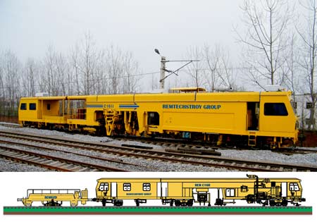
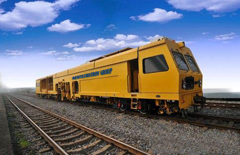
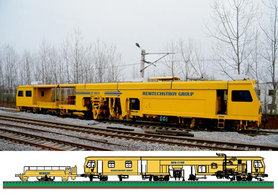
With the REM C16II/62D Switch Tamping Machine is mainly used to tamp in switch area, while it can also tamp on track line. The machine is applicable for lifting, lining, leveling, tamping, sweeping and shoulder consolidating for railway construction, overhaul and maintenance. Switch Tamping Machine is applicable for 50, 60, 68, 75kg/m rails, wooden or concrete sleepers (1667pcs/km for type concrete sleepers; 1680-1840pcs/km for type II concrete sleepers), crushed stone track bed, single line, double or multiple line with line spacing 4.0m and above.
The vehicle has the following features: • Japan HITACHI powershift transmission. • Tamping units for tamping of one sleepers (16 tamping tools). • Roller lifting and lining units with a total of four roller clamps. • Articulated trailer REM62D* (* Additional option: REM two stabilization units modul). • The machine is applicable in rainy day, night and heavy wind and dust circumstances. • Continuous working time is no less than 6 h. • Computer control system is provided with track line parameter input function which can realize auto, semi-auto or manual control of tamping operation. • Computer control system can automatically record, print and dump measuring results of working quality including track line level, superelevation, versine, distortion and working distance. • The tamping machine is fitted with one set of laser guiding system for lining control on flat and straight line. Guiding distance of laser shooting device is no less than 3000m.
• Shoulder vibration consolidar is composed of vibrator, elevating limitting devece, vibration reducing and locking unit.
The REM C16II - Switch Tamper is a first generation high output fully automated REM Tamping Machine, special development and design by R&D Center “REM" with possibility for manufacture at stage zero in a REM plant by request of the client. This is a first generation of REM machine, automated with built – in autonomous systems: for full remote control, for on-line diagnostics during operation, radars, georadars, GPS, 3D control and other REM systems. Our clients obtain a new class of Switch Tamper and Dynamic Stabilizer Unit with 18 month REM warranty, with high trustiness, high reliability and with high range of working tramsfer speed of up to 2 km/h.
/See the full technical specification of the machine below./
With the REM C16II/62D Switch Tamping Machine is mainly used to tamp in switch area, while it can also tamp on track line. The machine is applicable for lifting, lining, leveling, tamping, sweeping and shoulder consolidating for railway construction, overhaul and maintenance. Switch Tamping Machine is applicable for 50, 60, 68, 75kg/m rails, wooden or concrete sleepers (1667pcs/km for type concrete sleepers; 1680-1840pcs/km for type II concrete sleepers), crushed stone track bed, single line, double or multiple line with line spacing 4.0m and above.
The vehicle has the following features: • Japan HITACHI powershift transmission. • Tamping units for tamping of one sleepers (16 tamping tools). • Roller lifting and lining units with a total of four roller clamps. • Articulated trailer REM62D* (* Additional option: REM two stabilization units modul). • The machine is applicable in rainy day, night and heavy wind and dust circumstances. • Continuous working time is no less than 6 h. • Computer control system is provided with track line parameter input function which can realize auto, semi-auto or manual control of tamping operation. • Computer control system can automatically record, print and dump measuring results of working quality including track line level, superelevation, versine, distortion and working distance. • The tamping machine is fitted with one set of laser guiding system for lining control on flat and straight line. Guiding distance of laser shooting device is no less than 3000m.
• Shoulder vibration consolidar is composed of vibrator, elevating limitting devece, vibration reducing and locking unit.
The REM C16II - Switch Tamper is a first generation high output fully automated REM Tamping Machine, special development and design by R&D Center “REM" with possibility for manufacture at stage zero in a REM plant by request of the client. This is a first generation of REM machine, automated with built – in autonomous systems: for full remote control, for on-line diagnostics during operation, radars, georadars, GPS, 3D control and other REM systems. Our clients obtain a new class of Switch Tamper and Dynamic Stabilizer Unit with 18 month REM warranty, with high trustiness, high reliability and with high range of working tramsfer speed of up to 2 km/h.
Drawing REMC16II Swithch Tamper
Drawing REMC16II Switch Tamper + REM62D Dynamic Stabilizer Unit Drawing REM32EXP Dynamic Tamping Expres + PPT50 Unit + PDB50 Unit
Specification Tamper REM C16II
Main dimensions (L × W × H):
31200 mm × 3160 mm × 4300 mm
Broad Gauge Track:
1435 mm
Mass, ton, not more:
85 ton
Maximum speed under own output:
90 km/h
Maximum speed in a train composition:
100 km/h
Emergency stopping distance:
≤ 400 m (straight railway, at a speed 80km/h)
Minimum radius of describing a curve:
180 mm
Maximum operation speed:
0 ~ 2 km/h
Operational efficiency:
not more than 40min when tamping one group of 16 single switch; 500m/h~650m/h for main line tamping
Technological tolerance of the machine in a process of operation:
minimum of 1750 mm, 3300 mm maximum
Operational accuracy
Longitudinal leveling precision:
≤ 4 mm
Precision Horizontal leveling:
± 2 mm
Maximum depth of tamping:
560 mm
Maximum lifting by level:
150 mm
Maximum displacement by axis:
± 150 mm
Engine
Model
German Deutz BF12L513C 12V
Rated power
348kW/ 2300r/min
Video REM C16II Tamper*** Photos NEW REM 48EXP Tamper
+ Dynamic Stabilizer REM62D The Dynamic Stabilizer REM 62D is a heavy duty stabilizer units trailer designed for final track dressing while attached to the rear of a a REMTECH (Continuous 32EXP Tamper). The REM62D is a self contained unit equipped with two Dynamic Stabilizer Units and a diesel engine powered hydraulic system.
- Working transfer speed: 0 ~ 2.5 km/h - Тwo dynamic stabilizer units - Vertival static pressure: 0~2 x 120 kN
Drawing Dynamic Stabilizer Unit REM62D + New REM C16II Tamper Drawing New REM62D Stabilizer Unit
Photo REM62D Stabilizer
Specification
Length:
18,205 mm
Broad Gauge Track:
1,435 mm
Widht:
2,920 mm
Height:
3,920 mm
Weight:
56 ton
Travelling speed, max:
80 km/h
Minimal radius of curve negotiated (working/running):
300/150 m
Engine Power:
243kW
REM options:
FREE of charge REM options included in the contractual price as a standard delivery for the end customer: +Free option 1: The REMTECH to train Railways technicians on machine operation and maintenance in the REMTECH manufacturer plant. +Free option 2: The REMTECH to train Railways technicians on machine operating and maintenance in the country customers. +Free option 3: Technical documents for operating, maintenance and repairs as well as spare parts catalogues in English language. +Free option 4: All the plans and list of spare parts on CD. +Free option 5: Adjustment of the machine as per the requirements of the Buyer. +Free option 6: Air - conditioning system in the control cabins. +Free option 7: Equipped with 4 buffers CAT A according to UIC 526-1 and etc.
ADDITIONAL OPTIONS against assitonal payment at client's desire:
Customer Login and Price
Customer Login and prices To be able to access our prices, delivery terms, catalogs, brochures, technical specifications, videos, certificates, photos and pdf, you have to be registered, logged in and be a member of the "PRO Membership levels - www.tampers.org": - End customer PRO - owner of railway mechanization; - REM Agent/Dealer *P&T* (Wholesale I); - REM Agent/Dealer LT *P&T* (Wholesale I); - Wholesale PRO *P&T* (Wholesale II); - REM Agent/Dealer UA *P&T* (Wholesale III); - Wholesale KZ *P&T* (Wholesale III); - Customer KZ *P&T*; - REM Agent/Dealer {not EU} (Wholesale I); - Wholesale PRO {not EU} (Wholesale II); - Wholesale {not EU} (Wholesale III); - Customer {not EU}.
Not a tampers.org user yet? Register now free-of-charge and without obligation: 1) Load in your browser: www.tampers.org ; 2) Registration -> press " Register" top right or for Authentication -> press "Sing in", enter USED ID/Pass; To receive the Customer Login Name/Pass and Authentication for PRO Membership levels {www.tampers.org}, must necessarily send fax inquiry on company form with signature and stamp to the attention of Sales Department "REMTECH" or REMTECHSTROY GROUP, fax: +359 52 319990 or e-mail: sale@remtech.info or or contact directly the REMTECH representative in Your country.
+REM CCTV: Video surveillance system. Protective function: Warning upon attempts for penetration by foreign persons during the stay of the machine at stations. The video surveillance option may be used for visual survey/inspection of the machine and protections of its most important parts – cabin, operating elements, power cables and electronics. +REM Pilot GPS: System for collection and recording of control data and operating parameters of the main operating elements, as well as parameters of motion and determining of current location of REM 32EXP Dynamic in real time through a GPS. +REM Radar: System for safety and protection of the working staff and team servicing the REM 32EXP Dynamic operation, through automated location of objects moving along the rail road through a radar technology. Range of location of trains at a distance farther than 5000 meters. Velocity of moving of an object 10-300 km/h. Time for reaction of the radar and issuance of a warning signal: up to 15 seconds. +REM Georadar Measurements - RGM : Automated system for georadar (ground-penetrating radar) roadbed inspection REM GEOSCANNER is intended to provide the following solutions: - determining thickness and lithologic structure of the ballast bed discriminating the fouled subgrade layer and increased moisture areas; - localizing the upper boundary of roadbed soils and their lithologic structure; - discriminating low coherence areas in the roadbed featured by reduced density and increased moisture; - revealing foreign objects in the roadbed and ballast bed, viz., cables, buried track superstructure components (crossties, rails), large stones, etc. - localizing engineering facilities; - localizing areas with laid geotextile or expanded polystyrene; - inspection of quality of the accomplished track overhaul. The objective of this method of investigation is to determine the pollution within the ballast bed and the mixture of ballast with the subsoil. It is also possible to locate water traps. The qualitative measurement of the water content in the subsoil enables the existing drainage quality to be assessed. By comparing the condition before and after the rehabilitation, it was possible to make a quality assessment of the formation rehabilitation work performed.
Technology The REM Georadar Measurements - RGM is state of the art for GPR systems. It is based on more than 20 years of working experience with GPR and it is the product of continuous development and adaptation to the specific requirements of our international railway customers. - Survey of tracks of any length or even of the entire railway network. - High speed survey of 900 track kilometres per run. - 2,000 scans per second. - Each channel is controlled separately, allowing even speeds of more than 300 kph. - Three or even more longitudinal profiles provide track cross section at any position. - Measurement only between sleepers to avoid disturbances. - Scan distance between 2 cm and 60 cm for coping with all customer requirements. - Antennae frequencies between 100 MHz and 900 MHz for high resolution in all depths. - System-embedded positioning radar for accurate allocation of all measuring data along the entire track. Accuracy better than 0.5 m. - System-integrated DGPS for reception of world wide satellite systems GPS and GLONASS. Correction data for GPS via GSM or EGNOS for an accuracy better than 0.3 m. - Displaying of survey track and all constructions in Google Earth. - System-integrated Video-camera for continuous view of survey track. - System-specific Viewer-programme for display of the GPR results related to the geotechnical conditions of the track, including Google-Earth-view and Video-camera-pictures.
The RGM survey provides continuous details of track conditions. Railway engineers obtain important information about: - Thickness of track bed and sub-ballast layer. - Sections with clean or fouled ballast. - Drainage problems in ballast bed and undertrack. - Mapping of load-bearing problems (settlements, ballast pockets). - Anomalies along the track. RGM - Radargram with longitudinal profile of track section The picture shows a track section between km 11.100 and km 11.700. In that section the ballast has been renewed to a depth of 0.3 m. Below, there is fouled ballast (dark grey layer). Ballast settlements indicate insufficient bearing capacity of the sandy formation. Below the sandy layer, a drilling at km 11.450 is showing peat and clay. The picture shows a track section between km 1.300 and km 1.900 (see horizontal axis). The vertical axes represent both depth in m related to top of sleepers and travel time of the waves in nanoseconds. In that section the ballast has been renewed to a depth of 0.5 m (pale grey layer). Below, there is fouled ballast (dark grey layer). Ballast settlements can be seen between km 1.460 and 1.570. This is an indication for insufficient bearing capacity of the sandy subgrade (yellow layer). Below the sandy formation there is clay to be found. Between km 1.600 and km 1.900 the clay layer is almost adjacent to the ballast bed. In this section, a well working drainage is important. Otherwise water will remain inside the track, leading to eventual stability problems of the track. The picture shows crossings at km 1.370 and km 1.870. Drillings have been carried out at km 1.550 and km 1.740. In both cases ground water has been found in a depth of 1.2 m.
Quality control of track construction Track construction is always very cost-intensive. That's why at least the result should add up. Our quality control is continuous and exact. And we provide information about: - Quality of new ballast (cleanliness). - Thickness of track bed and sub-ballast layer. - Efficiency of track drainage. - Evenness of ballast-bed bottom or sub-ballast layer. - Track cross-section. RGM - Viewer showing the geotechnical track conditions. Diagram of long-profiles, cross-section; Video as well as track course on Google-Earth
Examples cables, pipes, objects Example for a cable crossing at km 14.094 in the formation in a depth of 1.20 meters. Example for a cable crossing at km 13.999,5 at the ballast base in a depth of 0.42 meters. Cables, pipes and objects in various depths between 0.16 m and 1.36 m along a range of about 30 meters.
+REM 3D RAIL - perfected a solution for 3D machine control. Use Rem3DRail for controlling rail tamping machine. The universal solution for 3D machine control and for: - Improved return on investments (ROI); - Higher precision; Total station or global positioning system (GPS) via satellites, using GPS receivers. In combination with Rem3DRail, you can operate many position indicators, such as: Total station: - Leica - Spectra Precision - Topcon GPS solutions: - Topcon - Leica - Trimble - Javad - Ashtech - Spectra Precision - Sokkia REM 3D RAIL ballast cleaning machine to within a few millimetres of alignment. REM 3D RAIL allows operators to focus on other systems of the machine and dramatically reduces survey costs while increasing accuracy.
Input data
Rem3DRail works well with various models, for example, rail geometry and horizontal and vertical alignment with cross-slope. Input data is transmitted directly from an office computer, from a portable computer on the machine, or from a GSM solution to Rem3DRail. You can also enter data manually by using the Rem3DRail keyboard.
Rem3DRail - The ultimate field surveying software and input units
Rem3DRail is compatible with various formats via surveying and design applications for PCs, for example: - DXF - DWG - ASCII &nb sp;- Land-XML - AnPakke - Excel
One unit in the operator’s cab Rem3DRail is housed in one unit, including an 8.4” high-resolution color display. An optional keyboard, light bar, and alarm are also available.
High Precision Rem3DRail continuously determines exact positions of machines’ mechanical equipment by: - Reading distances and angles in relation to the total station, or - Reading coordinates received from GPS receivers.
Position continuously displayed The display shows updated information about the section (chainage) offset, cross-fall, and vertical deviations. Operators can instantly and easily get information on current data, such as angles, distances, and coordinates.
3D control You avoid problems such as vertical curves, cross-slope transitions, and changes in width—thanks to Rem3DRail’s 3D machine control. Rem3DRail always adjusts the machine’s position or its moving tools, under all conditions—regardless of surface appearance or characteristics.
Safer working environment You increase work site safety because no one is needed outside the machine to check the position. Rem3DRail reduces idle time and unnecessary equipment deterioration. Fatigue and risk of injuries are also reduced.
Improved ROI Rem3DRail considerably cuts machine and labor costs. No job is too small for Rem3DRail, which enables: - Increased production output - Higher precision - A reduction in use of construction material - Decreased staffing needs Guarantee Rem3DRail comes with a two-year guarantee on component parts. You can extend the guaREM Remote Controlra ntee through a service contract.
+REM R/C (Remote Control) - Remote control of REM Rebuilt 08-32 machine. Actuating and stopping of the operation process. The remote control of the running the Tamping Units and Tamping. Emergency stop of the machi- Drainage problems in ballast bed and undertrack.ne.
+REM Doctor ODS (On-line Diagnostics System) - The On - line diagnostics system can be used in all models of REM mechanization with the purpose of control of the operation status and operation assessment of the technical status of main units and apparatus, guarantee and post – guarantee operation control by a REM servicing centre. The systems gives opportunity for archiving of parameters liable to diagnostics, prognostics on the working capacity and the motor capacity of railway mechanization in general for the whole machine and separately of each unit and apparatus. The system integration with REM Pilot GPS system, gives opportunity for creation of a fully automated working positions ( railway enterprise dispatcher, direction, servicing centre etc.), gives further opportunity to obtain information in real time mode for the GPS location of the machine, and for the working parameters of operation with the purpose of entire control of the equipment used upon work in “windows”, preventive control and avoidance of failures of expensive units and apparatuses.
The system is used for:
operating assessment of the technical status of units and apparatus, and reducing the risk of failure of the equipment upon work in “windows”;
considerable reduction of expenses for servicing and repair of the machine compared to the collection of statistics data upon various operation modes of the equipment, the information collected in the form of database of the system can be used for implementation of scheduled – preventive types of repair;
collection and uniting of the whole information entering from the machine control system, as well as control sensors of the system for diagnostics and sensors of the technological and auxiliary equipment;
registration of the parameters of the technical state of the main units and apparatuses upon various operation modes;
visualization of a detailed and complete “picture”: control and warning information to the machinist and the servicing staff;
GPS / Internet data transmission, alarming upon overload through a SMS;
Emergency stop of the engine (unloading from the overload) upon measurement of critical parameters (risk parameters of operating) of operating units and apparatuses, with continued recording of the parameters after full stop of the machine.
Showing each sensor is visualized in real time in a respective background for each unit, total of three colours: green – normal; yellow – attention; red – overload.
+REM Laser Using a REM laser system (levelling and lining laser) with a REMTECH tamper, gives the opportunity for simultaneous measurement of alignment and longitudinal level faults using a dot laser beam which strikes a laser receiver camera. With this REM system the measurement speed is designed to meet the optimal speed and stability ratio for both measurement drive and working drive of the REMTECH tamping machines, giving best possible accuracy for the measurement and long measurement distance for each drive. The Laser device uses very high measurement speed (over 500 measurements for second) to produce profile data for the curves when it is used with measurement coaches. The system allows to control the geometry of the railway in several hundreds of meters ahead of the operating REMTECH tamper, giving a resolution of up to 0.01% of the measuring range. Additional option: By wish of the client, there is an option for the REM Laser transmitter trolley to be made fully self – propelling with full REM Remote Control from the control cabin of the REMTECH tamper. This gives opportunity to fully eliminate the need of additional staff on positioning of the levelled section of the отсечка railway.
Specification
Resolution of the receiver:
< 1.00 mm
Measuring distance:
up to 350,0 m
Measuring speed:
up to 500 meas/sec
Serial or amalogue interface
+REM TM-System - REM TM-System represents a System intended to increase the working speed of the REMTECH and Plasser tamping machine. As of 2011, the REMTECH Track-Laying Machines have been using the REM TM-System track measuring system for pre-measuring for REMTECH and Plasser tamping machines. The innovative system records the data digitally and forwards the values to the REM computer of the tamping machines in digital flow.
REM TM-System benefits: - High productive pre-measuring system for tamper; - Compact and cordless; - Storage of all relevant railway measurement values; - Continuous data flow; - Cost reduction due to high efficiency and railway staff reduction;
The measuring equipment is operated by two persons. After storing information in a file, the measurement basis is set up. A radio link between wagons ensures data exchange. The first fixed point of the measuring chord is then defined. The tachymeter wagon then rolls to the next point and the measuring procedure is repeated. After the wagon has been moved to the chainage of the first fixed point, the distance between the wagons is measured. The REM prismatic wagon gradually moves towards the tachymeter wagon. At the same time, the displacement and lift values of the track are calculated based on the track's design axis and the data is saved every five metres. The railway operator copies the data from the field computer onto a USB stick, imports it into the software on their laptop and creates the tamping file with lifting and aligning values, which they then transfer onto a tamping disc of the REM or Plasser machine. In addition, it can also define the superelevations and track gauge.
Specification
Gauge measurement - Rande:
- 20 mm to + 60 mm
Gauge measurement - Accuracy:
+/- 0.1 mm
Gauge:
1000 mm, 1067 mm, 1435 mm, 1520 mm
Cant measurement - Rande:
+/- 10 degrees or +/- 265 mm
Cant measurement - Accuracy:
+/- 0.5 mm (static)
Interfaces:
USB, RS232,WiFi, Bluetooth
General
Application Tamper:
Pre-measuring for tamping
Field of use:
- New construction railway - Renewal railway - Maintenance railway
Supported total stations:
Trimble
Measurement performance:
up to 1400 m/h in Go/Stop mode more thet 2200 m/h in kinematic mode
REM TM-System+Soft opportunities: - Merge stand points from REM Track measurement; - Data analysis and Ramp definition; - Support for maximum and minimum lift, maximum shift; - Special functions (constained poinds and platforms); - Third windows to display the supereelevation error; - Generation of synchronize file for Plasser and REM tamping machine; - Export for tamping machine (Dos-ALC, Win-ALC, REMTECH, Matisa, Plasser, CGV-format).
+ Dynamic Stabilizer REM62D The Dynamic Stabilizer REM 62D is a heavy duty stabilizer units trailer designed for final track dressing while attached to the rear of a a REMTECH (Continuous 32EXP Tamper). The REM62D is a self contained unit equipped with two Dynamic Stabilizer Units and a diesel engine powered hydraulic system.
- Working transfer speed: 0 ~ 2.5 km/h - Тwo dynamic stabilizer units - Vertival static pressure: 0~2 x 120 kN
Drawing Dynamic Stabilizer Unit REM62D + New REM C16II Tamper Drawing New REM62D Stabilizer Unit
Specification
Length:
18,205 mm
Broad Gauge Track:
1,435 mm
Widht:
2,920 mm
Height:
3,920 mm
Weight:
56 ton
Travelling speed, max:
80 km/h
Minimal radius of curve negotiated (working/running):
300/150 m
Engine Power:
243kW
+ Ballast Management PDB 50 The Double Broom PDB 50 is a heavy duty double broom trailer designed for final track dressing while attached to the rear of a a REMTECH (Continuous 32EXP Dynamic Tamping Express). The PDB 50 is a self contained unit equipped with two hydraulically driven ballast brooms and a diesel engine powered hydraulic system.
Drawing New REM 32EXP Dynamic+ PDB50 Drawing PDB50
Specification
Length:
8,636 mm
Broad Gauge Track:
1,435 mm
Widht:
2,134 mm
Height:
1,829 mm
Weight:
12,8 ton
Travelling speed, max:
80 km/h
Wiheel Diameter:
711 mm
Engine Power:
240HP
++ Ballast Management PPT 50 The Plow Trailer PPT 50 has a heavy duty trailer mounted x-type transfer plow and shoulder profiling wings. The shoulder profiling wings allow ballast to be retrieved and brought into the transfer plow for distribution while profiling the shoulders to the proper slope angle. The front trailer operation is controlled by the operator of either a REMTECH (32EXP Dynamic Tamping Express).
Drawing New REM32EXP Dynamic+ PPT50 Drawing PPT50
Specification
Length:
7,518 mm
Broad Gauge Track:
1435 mm
Widht:
2,540 mm
Height:
1,524 mm
Weight:
14,9 ton
Travelling speed, max:
80 km/h
Wiheel Diameter:
711 mm
The integrated system of REM is without any analogue in the world and is not offered as an option by the original production plant of the machine and units – Plasser Austria. The application of complex measures for control and protection of those expensive units gives a real and proven with references increase in 2 and more times: motor operation life in years of flawless operation, or number of cycles of tamping after integration. The said technology has been used for 12 years upon capital repair of heavy mechanization in large infrastructure companies clients of our concern (available references), or upon the offered new railway mechanization of REMTECH (machines of second generation) manufactured after 2010.
Technically, the modernization of a base machine through various options REM systems (without analogue, original production and design of REMTECH), principally this is the base for offer to our clients of a complex guarantee without analogue in the world, comprising 18-24 months, against maximum offered guarantee of the Plasser concern, or another one for a new machine within not more than 12 months. All this is in the name of the clients, contact is, this could become true for Your mechanization. For contact REMTECH.
Presently our China Railway Group is intending to purchase ballast regulator(1),tampers(2),track stablizer(1) for carrying out a project in Malaysia. If your company can give us a CIF price and time of delivery on any machine I mentioned above,we...




 yellow – attention;
  red – overload.